How to Build a Bench Power Supply From ATX - Part I
In this post, I'll show you how to create a bench power supply from an ATX power source.

Posted by Nuno Alves on Jun 08 2021
Article in english
2 min · No views · No likes
I needed a bench power supply for testing, fixing, and building my electronics and IOT projects. Despite the fact that I could buy one, I decided to recycle an ATX power source I had stored, and create a new bench power source from it.
For that, I started defining my requirements. I would need:
- One 3.3V output
- Two +5V output
- One +12V output
- One -12V output
- Two USB outputs
- A variable output (voltage and current), between 1.25-25 Volt and 0-2 Amperes
With this, I could get any (variable) voltage between 1.25V to 25V and also a combination of any of the fixed ones.
As a requirement, I also want to have a power switch (on/off), a power-on LED (red), a standby LED (green) and another switch for turning on/off the variable output independently. And, as a final touch, a digital multimeter embedded for the variable output.
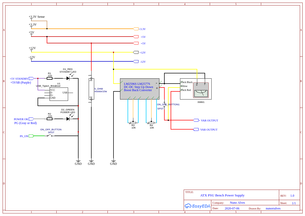
This is the circuit schematic, with the requirements above
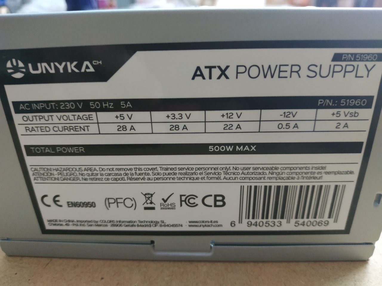
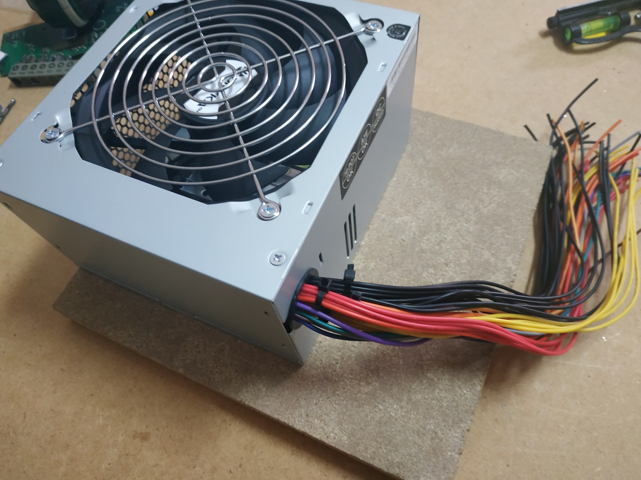
So, let's get started. I used this ATX, with output voltages and currents identified on it
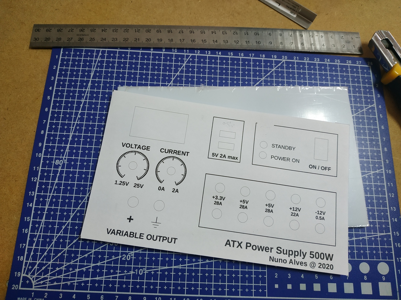
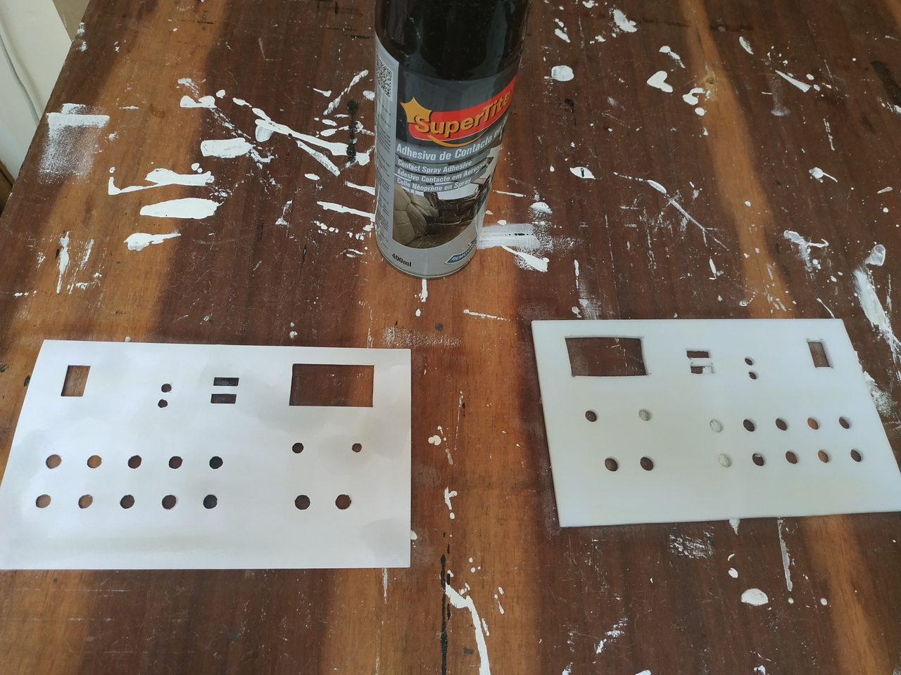
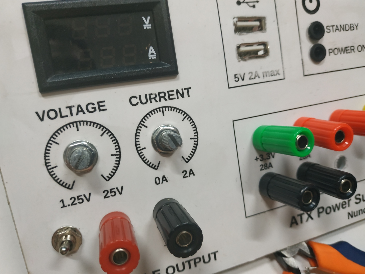
I also designed my front panel, printed it and transfer the design to an acrylic board
Then I drilled it according to the design and glued a new printout. After that, I've applied an acryl base to it
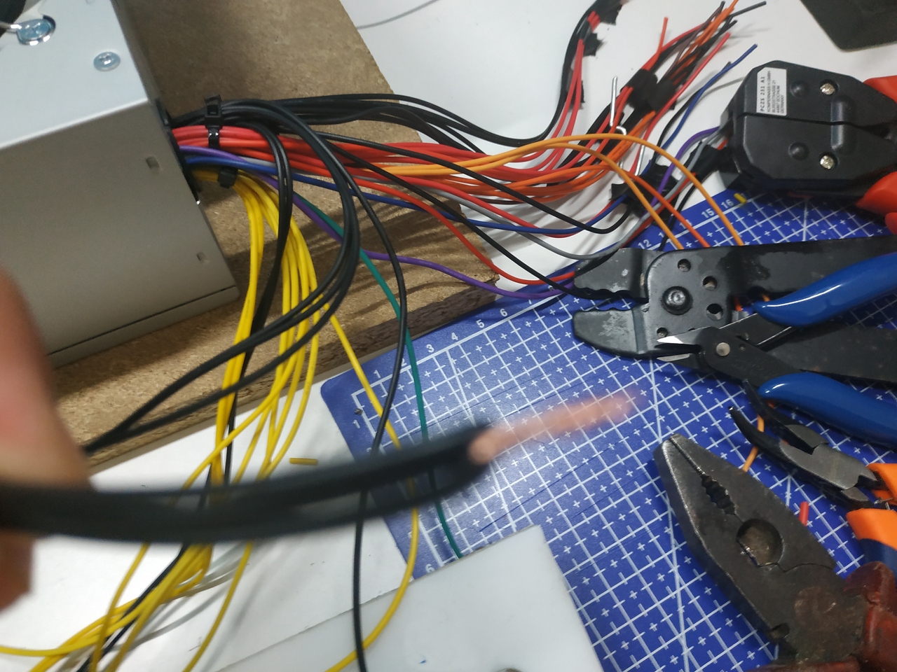
Then... wiring time! Cut the connector from the ATX power source and group wires by output voltages (or colors). I've tried to make groups of 3 so that they could handle the maximum amperage described with no problems
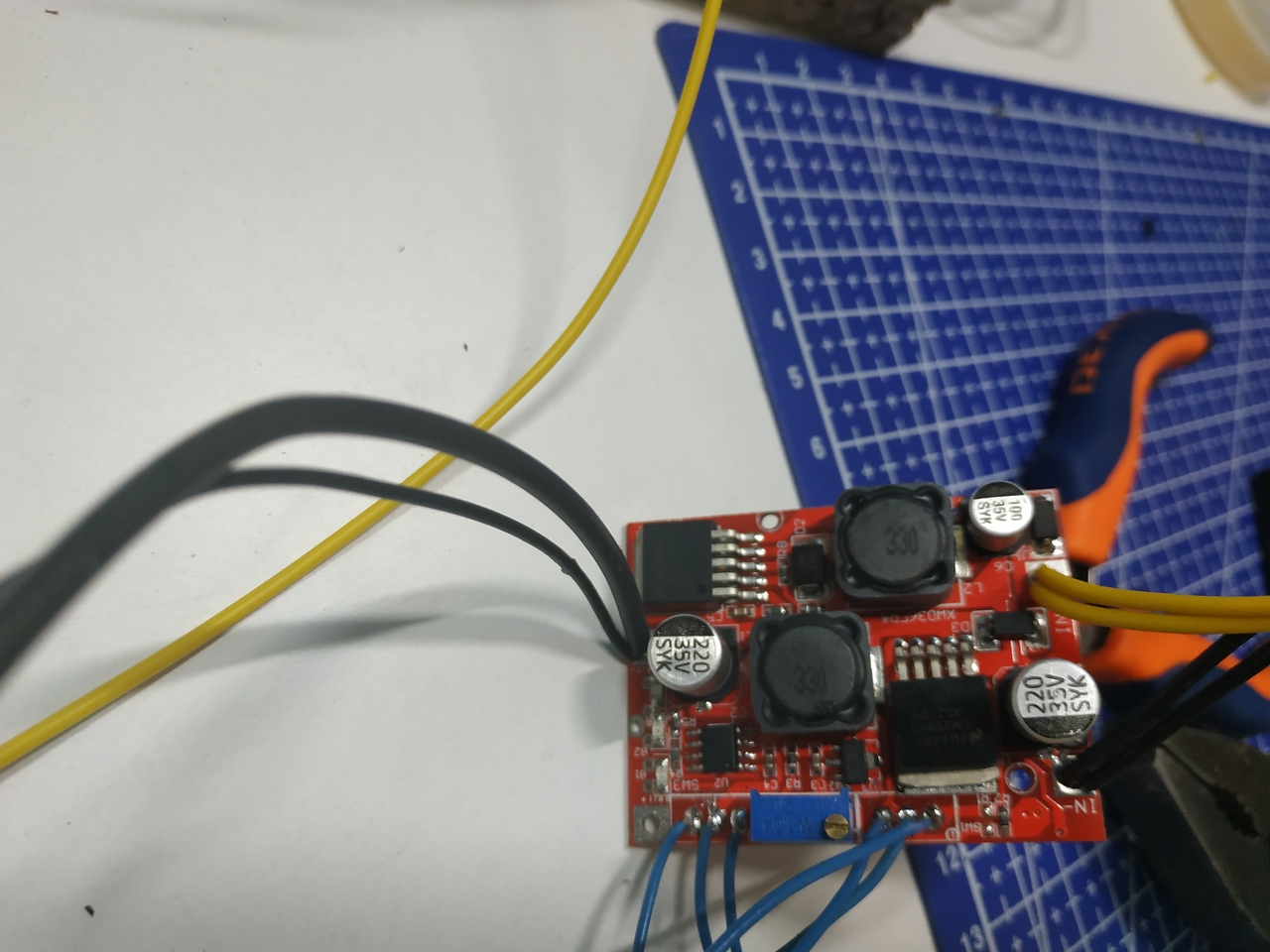
For the variable section, I've unsoldered Boost Buck converter potentiometers and soldered the new ones with wires, so that they could be attached to the front panel. I've also soldered power input from the ATX and the Digital Multimeter on it
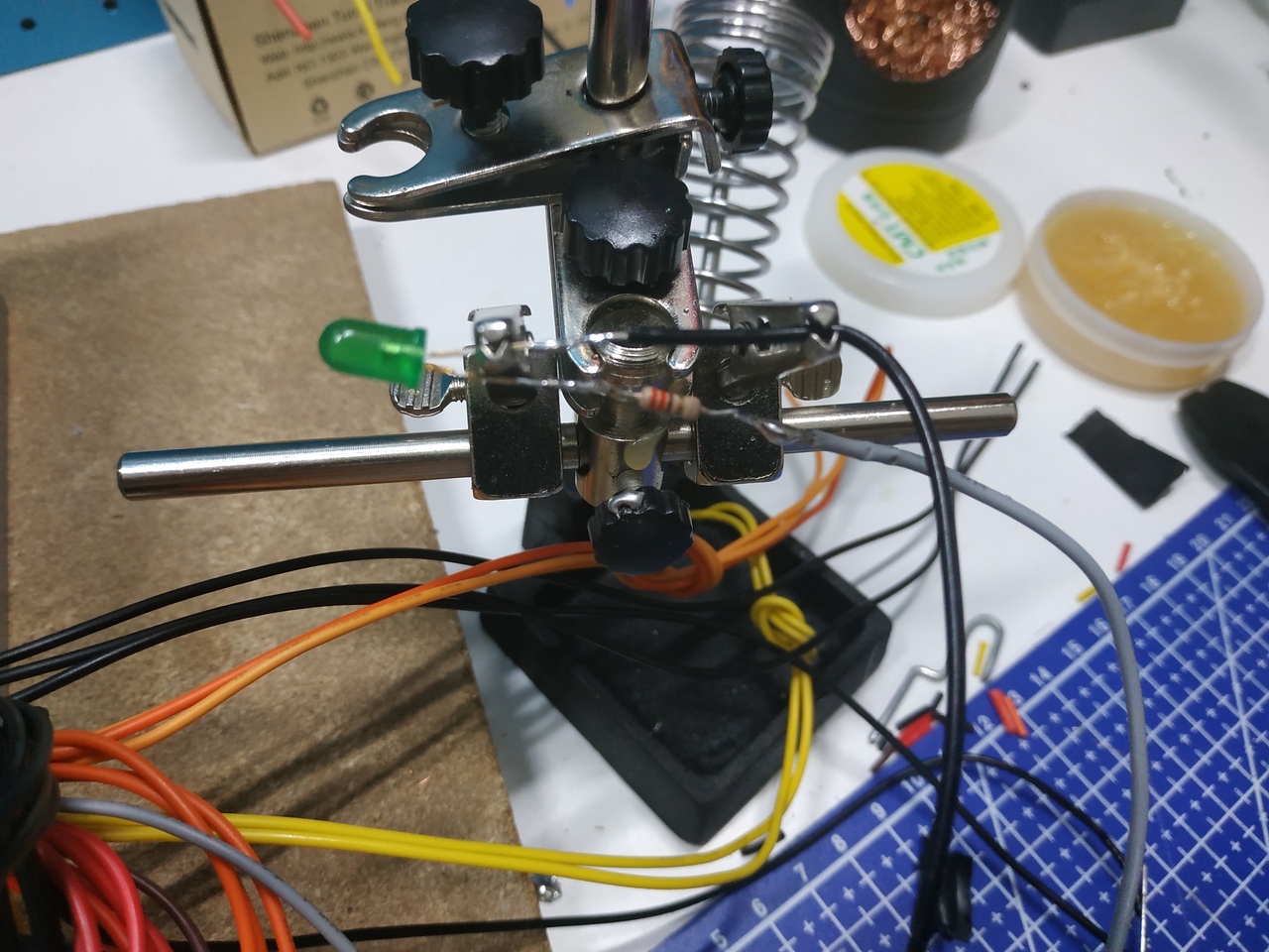
Finally, we can proceed with power output connectors, USB, Power On and Standby LEDs wiring
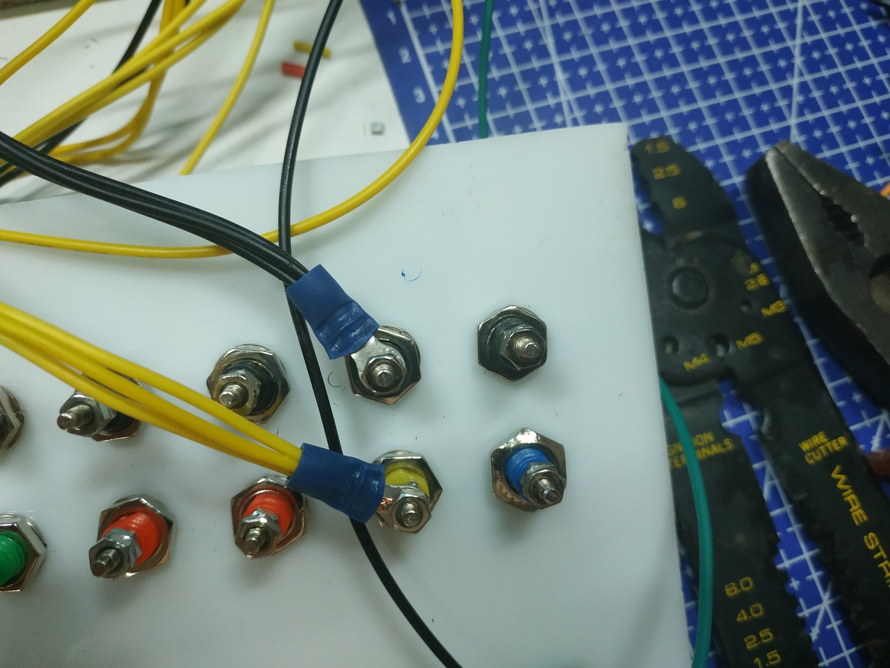
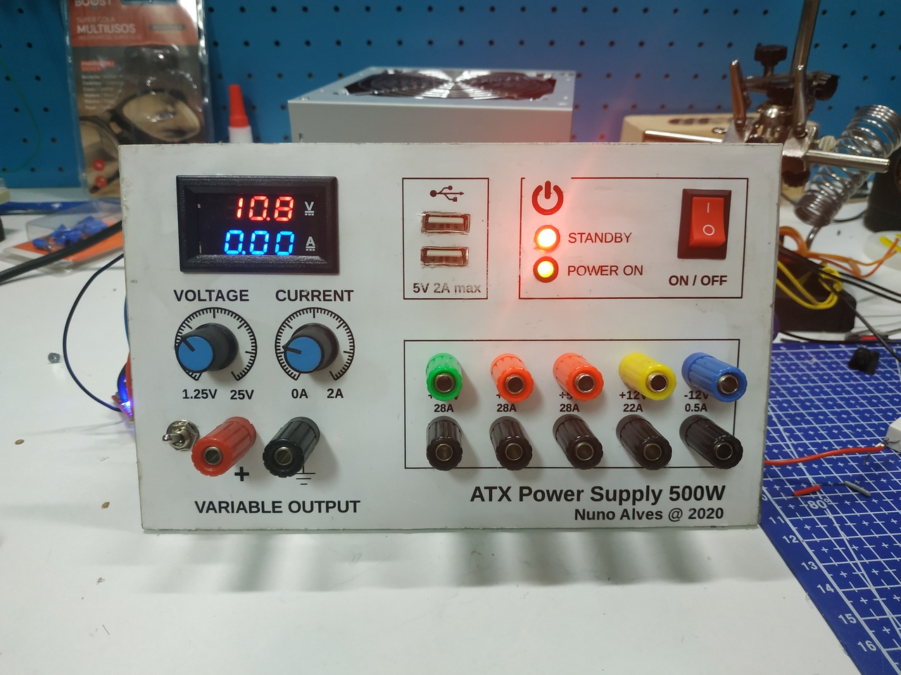
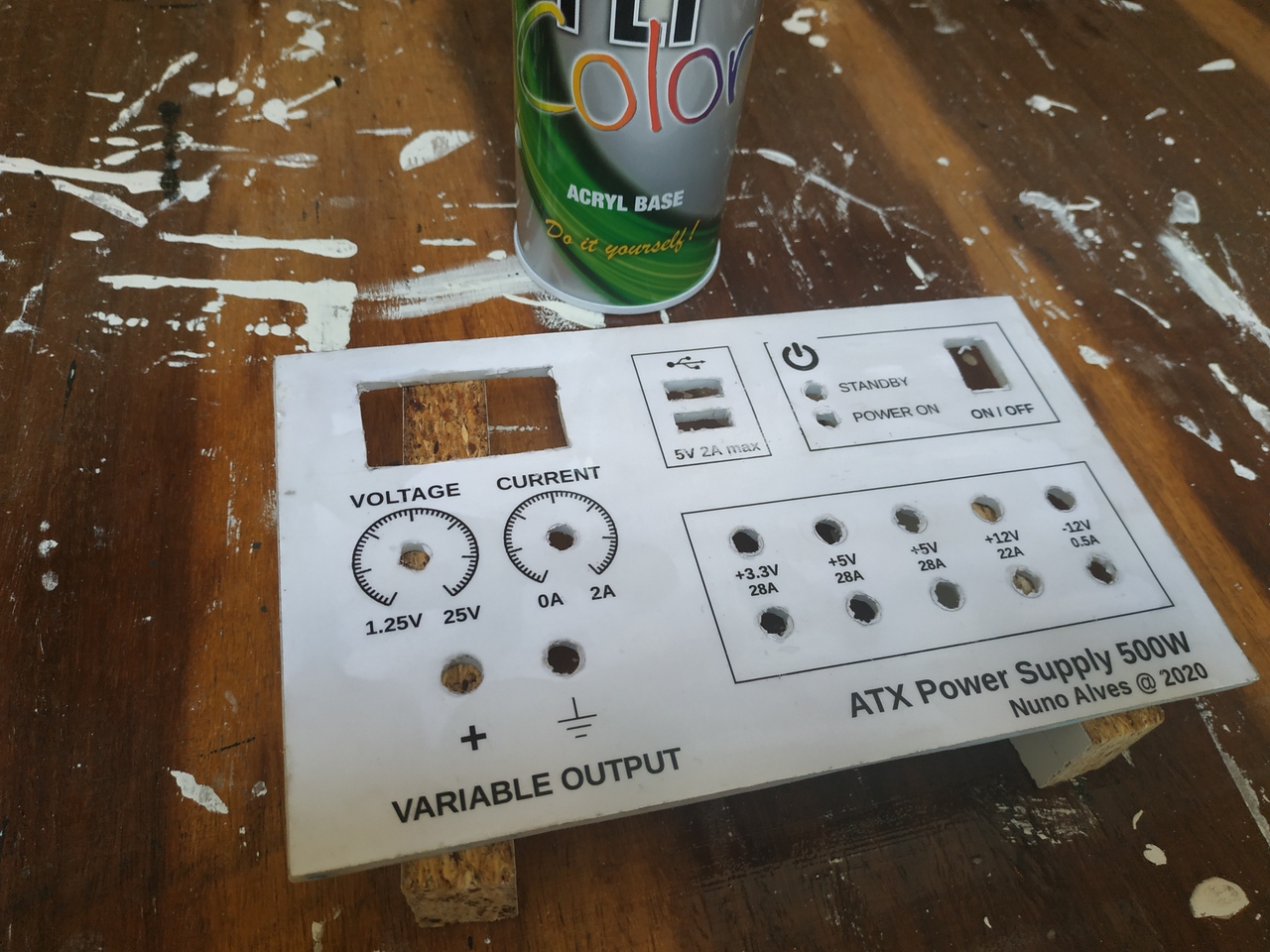
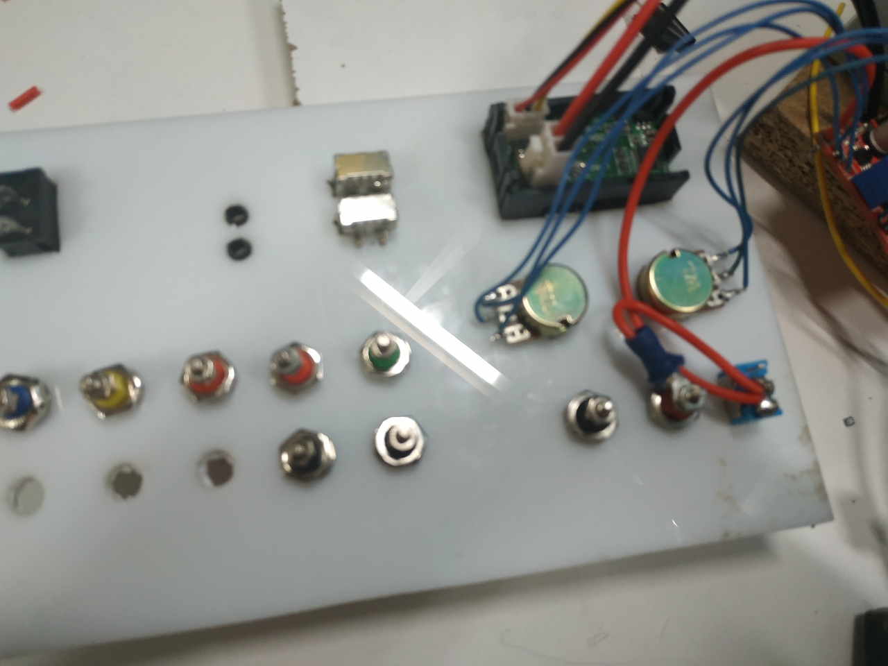
This is the final result, after everything attached to the panel, wired and connected
In Part 2 of this tutorial, I'll show how to do a suitable case for the bench power supply.
And that's it!
If you like this post, click Like button below. You can also share your comments or suggestions with me.